
Petrochemical Plant Design
Petrochemical plant design is a multidisciplinary undertaking that blends chemical engineering principles with mechanical, civil, and safety considerations to transform hydrocarbon feedstocks into a broad spectrum of chemical products. Mast…
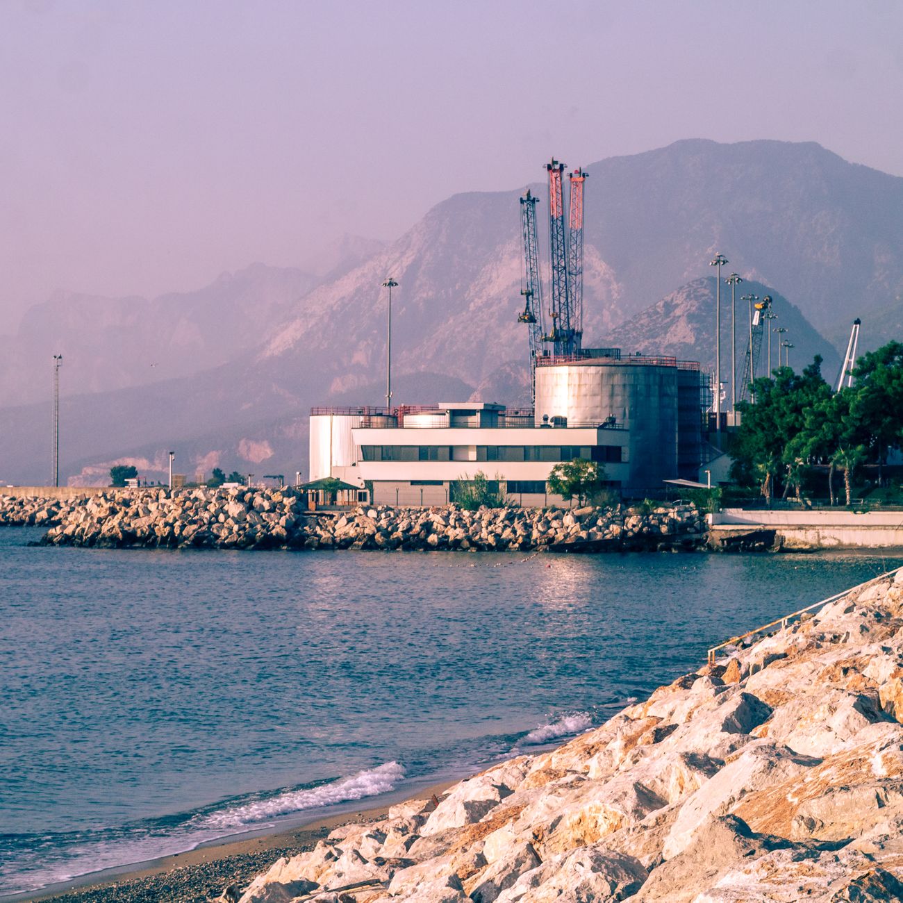
Petrochemical plant design is a multidisciplinary undertaking that blends chemical engineering principles with mechanical, civil, and safety considerations to transform hydrocarbon feedstocks into a broad spectrum of chemical products. Mastery of the terminology used throughout this field is essential for engineers, designers, and operators who seek to optimize performance, ensure safety, and comply with regulatory standards. The following exposition presents the most important terms and concepts encountered in the design of a modern petrochemical complex, illustrating each with practical examples and highlighting typical challenges that may arise during implementation.
Feedstock refers to the raw material introduced into a process unit. In a petrochemical context the feedstock is usually a fraction of crude oil such as naphtha, light gas oil, or a specific stream like ethane extracted from natural gas. The selection of feedstock determines the downstream product slate, the required processing conditions, and the overall economics of the plant. For example, an ethylene cracker typically uses ethane or naphtha as feedstock; the choice influences the energy consumption because ethane cracking demands lower temperatures but higher steam ratios, while naphtha cracking yields a richer mixture of C2–C4 olefins but requires more complex fractionation.
Conversion is the fraction of the feedstock that is transformed into desired products. It is expressed as a percentage and is calculated by dividing the mass of converted material by the mass of feedstock entering the unit. High conversion rates are often pursued to maximize utilization of the feedstock, yet they may also increase the formation of by‑products and impose harsher operating conditions. In a steam reformer producing synthesis gas, conversion of methane may approach 99 % at temperatures above 800 °C, but achieving such levels requires careful control of catalyst deactivation and heat management.
Yield denotes the proportion of a specific product obtained relative to the amount of feedstock processed. Unlike conversion, which measures the extent of reaction, yield focuses on the amount of a target compound. For instance, a polypropylene plant may report a propylene yield of 75 % based on the naphtha feed, meaning that 75 % of the carbon atoms in the feed end up as propylene molecules after cracking and separation.
Selectivity describes the preference of a reaction pathway toward a particular product when multiple reactions are possible. It is calculated by dividing the yield of the desired product by the overall conversion. High selectivity is advantageous because it reduces the need for downstream separation and minimizes waste. In an alkylation unit, the selectivity toward isobutane‑based alkylate can exceed 95 % when operating at optimal temperature and catalyst concentration, thereby limiting the formation of light gases that must be recycled.
Reaction is the fundamental chemical transformation occurring within a reactor. Reactions can be categorized as exothermic (releasing heat) or endothermic (absorbing heat), and they may be homogeneous (occurring in a single phase) or heterogeneous (involving solid catalysts). Understanding the kinetics and thermodynamics of a reaction is essential for sizing reactors, selecting operating conditions, and designing appropriate heat integration schemes. An example of an exothermic reaction is the hydrogenation of benzene to cyclohexane, while the steam‑reforming of methane is a classic endothermic process.
Reactor is the vessel where the chemical reaction is carried out. Reactor designs vary widely, ranging from simple plug‑flow tubes to sophisticated multi‑stage catalytic reactors with internal heat exchangers. The choice of reactor type depends on factors such as reaction order, heat removal requirements, catalyst form, and pressure drop constraints. A common configuration for olefin cracking is the tubular furnace, where a series of heated tubes provides the high temperature (≈850 °C) needed for rapid cracking while maintaining short residence times to limit secondary reactions.
Catalyst is a substance that accelerates a chemical reaction without being consumed. Catalysts are often solid materials dispersed in a reactor, providing active sites for reactant adsorption and transformation. In petrochemical processes, catalysts are tailored to promote specific reactions and to resist deactivation mechanisms such as coke deposition or sulfur poisoning. For example, zeolite‑based catalysts are employed in fluid catalytic cracking (FCC) to enhance the production of gasoline‑range hydrocarbons, whereas nickel‑based catalysts are preferred in steam reforming for their high activity toward methane conversion.
Coke is a carbonaceous deposit that forms on catalyst surfaces during high‑temperature processes, especially those involving heavy hydrocarbons. Coke buildup reduces catalyst activity and increases pressure drop, necessitating periodic regeneration or replacement. In an FCC unit, coke is removed by sending the spent catalyst to a regenerator where it is burned off with air, generating heat that can be recovered for process heating. Managing coke formation is a perpetual challenge, as excessive coke can lead to hotspot formation, catalyst fouling, and unplanned shutdowns.
Heat exchanger is a device that transfers thermal energy between two fluid streams without mixing them. In petrochemical plants, heat exchangers are ubiquitous, providing heating for endothermic reactions, cooling for exothermic reactions, and temperature control for separation steps. Shell‑and‑tube, plate‑and‑frame, and air‑cooled exchangers are common designs. The design of a heat exchanger must account for fouling factors, pressure drops, and material compatibility with corrosive streams such as sour gas. A practical application is the use of a recuperative heat exchanger to preheat naphtha feed using the hot product stream from an ethylene cracker, thereby reducing overall fuel consumption.
Distillation column is a vertical equipment used to separate components based on differences in volatility. Columns consist of a series of trays or packing sections that provide contact between ascending vapor and descending liquid. The performance of a column is described by its number of theoretical stages, reflux ratio, and separation efficiency. In a petrochemical plant, a fractionation column may be employed to separate cracked gases into ethylene, propylene, and heavier hydrocarbons. Design challenges include controlling foaming, managing tray wear, and ensuring adequate column internals to handle high vapor loads.
Fractionation denotes the process of separating a mixture into its constituent fractions, typically by distillation. Fractionation is central to the production of pure olefins, aromatics, and solvents. The design of a fractionation train must consider the relative volatilities of the target components, the presence of azeotropes, and the energy demand of reboilers. For instance, separating ethylene from a mixture of C2–C4 hydrocarbons often requires a series of de‑ethanizer, de‑propanizer, and de‑butanizer columns, each optimized for a specific cut point.
Process flow diagram (PFD) is a schematic representation of the major process units, streams, and equipment in a plant. The PFD provides a high‑level view that includes material balances, operating conditions, and key control loops. It serves as a communication tool between engineering disciplines and is the basis for detailed design. A typical PFD for an ethylene plant will show the feed pre‑treatment, the cracking furnace, the quench system, the series of fractionation columns, and the product storage facilities. Accuracy in the PFD is critical; omissions or incorrect stream labeling can propagate errors into the detailed engineering phase.
Piping and instrumentation diagram (P&ID) expands upon the PFD by detailing the piping, valves, instrumentation, and control devices for each unit. The P&ID is essential for construction, commissioning, and maintenance, as it specifies the exact locations of pressure transmitters, temperature sensors, safety relief valves, and shutdown logic. For a catalytic reformer, the P&ID will illustrate the steam injection manifold, the catalyst bed, the product gas outlet, and the associated temperature control loops. Properly annotated P&IDs help prevent construction errors, such as mis‑routing of high‑pressure steam lines.
Safety instrumented system (SIS) is an engineered safety function that monitors process parameters and initiates protective actions when predefined limits are exceeded. SIS components include sensors, logic solvers, and final control elements (e.G., Shutdown valves). The design of an SIS follows standards such as IEC 61511, which define safety integrity levels (SIL) based on risk assessment. In a hydrocracking unit, an SIS may be configured to close the feed valve and open a vent to relieve pressure if the reactor temperature exceeds a critical threshold, thereby preventing a runaway reaction.
Hazard and operability study (HAZOP) is a systematic technique for identifying potential deviations from design intent and assessing their consequences. HAZOP teams examine each process node, asking “what if” questions to uncover safety or operability issues. Findings from a HAZOP may lead to the installation of additional relief devices, changes in operating procedures, or redesign of equipment. Conducting a HAZOP early in the design of a polymerization plant can uncover risks associated with exothermic runaway, which can be mitigated by installing a fast‑acting cooling system and an automated emergency shutdown.
Heat integration is the practice of linking heat‑producing and heat‑consuming streams to reduce external energy requirements. Pinch analysis is a common methodology used to identify the minimum utility consumption and optimal heat exchanger network. For a typical petrochemical complex, waste heat from the FCC regenerator can be recovered to preheat the feed to the steam reformer, resulting in fuel savings of up to 30 %. The challenge lies in balancing the capital cost of additional heat exchangers against the operational savings, while ensuring that fouling and pressure drop remain within acceptable limits.
Material balance is the quantitative accounting of mass entering, leaving, and accumulating within a process unit. It forms the foundation for sizing equipment, estimating yields, and evaluating process efficiency. In a design calculation, the mass balance for an ethylene cracker will include the feed composition, the cracked product distribution, the recycle streams, and the losses to the quench water. Accurate mass balances are essential for environmental reporting, as they determine the quantities of emissions and waste streams that must be treated.
Energy balance complements the material balance by accounting for the heat generated or consumed throughout the process. Energy balances are crucial for sizing furnaces, boilers, and utilities. For example, the exothermic heat of combustion in an FCC regenerator can be quantified and then allocated to the steam generation system, reducing the need for external fuel. In practice, achieving a tight energy balance often requires iterative adjustments of heat exchanger networks and the inclusion of process integration studies.
Utility system encompasses the ancillary services that support the main production processes, such as steam, cooling water, compressed air, and electricity. Designing an efficient utility system involves selecting appropriate generation technologies (e.G., Cogeneration, waste heat boilers) and ensuring reliable distribution. A common challenge is the demand for low‑pressure steam in multiple units; this can be addressed by installing a multi‑pressure boiler with internal extraction points, thereby reducing the need for separate pressure-reducing stations.
Cooling water system provides the necessary heat removal for condensers, reactors, and auxiliary equipment. The design must consider the source water temperature, flow rate, and environmental discharge limits. In regions with limited water availability, a closed‑loop cooling tower may be employed, but this introduces additional fouling and maintenance considerations. Selecting corrosion‑resistant materials for cooling water pipelines, such as stainless steel or high‑alloy carbon steel, helps mitigate the risk of leaks and contamination of product streams.
Process control refers to the set of strategies and devices used to maintain process variables within desired ranges. Control loops typically involve measurement (temperature, pressure, flow), comparison with a set point, and actuation (valve adjustment, pump speed change). Advanced control techniques such as model predictive control (MPC) can improve product quality and reduce energy consumption by anticipating disturbances. In an olefin polymerization reactor, precise temperature control is vital to avoid polymer fouling and ensure consistent molecular weight distribution.
Instrumentation includes the devices that measure process variables and provide data to the control system. Common instruments are pressure transmitters, temperature sensors (RTDs or thermocouples), flow meters (Coriolis or ultrasonic), and level gauges. Selecting the appropriate instrument rating (e.G., Explosion‑proof, intrinsically safe) is essential for compliance with safety standards such as ATEX or IEC 60079. Instrument calibration and maintenance schedules are critical to avoid drift that could lead to unsafe operating conditions.
Reliability‑centered maintenance (RCM) is a methodology that focuses maintenance activities on equipment whose failure would have the greatest impact on safety, environmental, or production goals. RCM involves failure mode analysis, condition monitoring, and the development of preventive maintenance tasks. For a high‑pressure steam turbine supplying power to a petrochemical complex, RCM may dictate regular vibration analysis and oil sampling to detect bearing wear before catastrophic failure occurs.
Turnaround is a planned outage period during which major maintenance, inspection, and upgrades are performed. Turnarounds are resource‑intensive and require meticulous planning to minimize production loss. In a refinery‑integrated petrochemical plant, a turnaround might involve cleaning the FCC reactor, replacing catalyst, and inspecting the associated heat exchangers. Effective turnaround management relies on detailed work scopes, accurate labor estimation, and robust logistics coordination.
Process safety management (PSM) is a regulatory framework aimed at preventing catastrophic releases of hazardous chemicals. PSM elements include process hazard analysis, operating procedures, training, mechanical integrity, and emergency response. Compliance with standards such as OSHA 1910.119 Or the EU Seveso III Directive is mandatory for large petrochemical facilities. Implementing PSM often requires the development of detailed operating manuals, regular safety drills, and systematic tracking of equipment integrity.
Environmental impact assessment (EIA) evaluates the potential effects of a new plant on air quality, water resources, soil, and biodiversity. The EIA process involves baseline data collection, modeling of emissions, and mitigation planning. For a new ethylene plant, the EIA would assess the emissions of volatile organic compounds (VOCs), greenhouse gases, and waste water constituents, proposing control technologies such as condensers, scrubbers, and wastewater treatment plants to meet regulatory limits.
Emission control technologies are installed to reduce pollutants released to the atmosphere. Common devices include low‑NOx burners, catalytic oxidizers, and flue‑gas desulfurization units. In a reformer that produces synthesis gas, a selective catalytic reduction (SCR) system may be required to limit nitrogen oxide emissions below 100 ppm. Designing these systems involves careful selection of catalyst, temperature window, and reagent (e.G., Ammonia) injection strategy.
Corrosion is the degradation of metal components due to chemical reactions with the environment. In petrochemical plants, corrosion can be caused by sour gases (H₂S, CO₂), chlorides, or high‑temperature steam. Materials selection, corrosion‑inhibitor injection, and protective coatings are primary mitigation strategies. For example, carbon steel pipelines carrying sour gas may be internally coated with a corrosion‑resistant alloy, while external surfaces are protected with cathodic protection to extend service life.
Material of construction specifies the alloy or composite used for equipment in contact with process streams. Choice of material balances cost against resistance to corrosion, temperature, and pressure. Stainless steel 304L is common for moderate‑temperature, low‑corrosivity streams, while Inconel 625 is selected for high‑temperature, high‑chloride environments such as a chlorine recovery unit. Incorrect material selection is a frequent source of premature failure and costly repairs.
Pressure vessel is a container designed to hold gases or liquids at pressures substantially higher than atmospheric. Codes such as ASME Section VIII govern the design, fabrication, testing, and inspection of pressure vessels. In a petrochemical setting, pressure vessels include reactors, storage tanks, and separators. Key design parameters are design pressure, allowable stress, corrosion allowance, and wall thickness. Proper welding procedures and non‑destructive testing (NDT) are mandatory to ensure integrity.
Separator is equipment used to divide a mixture into distinct phases, typically gas‑liquid or liquid‑liquid. Common separators include knock‑out drums, three‑phase separators, and decanters. In a gas processing train, a three‑phase separator removes liquid hydrocarbons and water from the gas stream before compression. Design challenges involve ensuring adequate residence time for phase disengagement, preventing foaming, and selecting appropriate internals to handle high liquid loads.
De‑ethanizer is a specific type of distillation column that separates ethylene from heavier hydrocarbons. The column operates at low pressure to favor ethylene vaporization, with a reflux system that returns a portion of the overhead liquid to improve separation efficiency. The de‑ethanizer is often followed by a de‑propanizer and a de‑butanizer to achieve the desired product purity. Operational issues such as column flooding or tray damage can arise if the feed composition varies beyond design limits.
Reboiler supplies the heat required to generate vapor in the bottom of a distillation column. Reboilers can be of kettle‑type, forced‑circulation, or thermosyphon designs. The choice depends on the required heat duty, fouling propensity, and pressure drop considerations. In a FCC fractionator, a high‑efficiency reboiler provides the necessary heat to vaporize heavy residues, while a low‑temperature reboiler may be used for a de‑ethanizer to avoid ethylene polymerization.
Condenser removes heat from vapor streams to produce liquid product. Air‑cooled condensers are common where water resources are limited, while water‑cooled shell‑and‑tube condensers are preferred for high‑capacity applications. The design must address condensate removal, pressure drop, and potential fouling. For a propylene plant, a condenser must be sized to handle the latent heat of vaporization while maintaining a low enough temperature to prevent polymerization of the propylene.
Heat duty quantifies the amount of heat transferred in a heat exchanger, reboiler, or condenser. It is expressed in units of energy per time (e.G., MW or BTU/h). Accurate calculation of heat duty is essential for equipment sizing and utility planning. In a steam reformer, the heat duty of the furnace must match the endothermic demand of the reforming reaction, typically requiring several megawatts of furnace output.
Fouling factor is an empirical parameter used to account for the reduction in heat transfer efficiency caused by deposits on heat exchanger surfaces. Fouling factors vary with fluid composition, temperature, and flow velocity. Designers often include a fouling factor in the overall heat transfer coefficient calculation to ensure that the exchanger remains adequately sized over its service life. In a crude oil pre‑heat train, high fouling rates may necessitate frequent cleaning or the use of tube alloys with smoother surfaces.
Pressure drop is the reduction in fluid pressure as it flows through equipment such as pipes, valves, or reactors. Excessive pressure drop increases pumping costs and may lead to inadequate flow rates. Calculations use correlations such as Darcy‑Weisbach for pipe flow and empirical formulas for packed beds. In a catalytic reformer, pressure drop across the catalyst bed must be limited to maintain the desired residence time and to avoid excessive compression energy.
Turn‑down ratio defines the range over which a unit can operate relative to its design capacity. A high turn‑down ratio provides flexibility to handle feedstock variations or market demand fluctuations. For an ethylene cracker, a turn‑down ratio of 0.5 (I.E., Operation at 50 % of design capacity) may be required to accommodate seasonal feedstock availability. Designing for a wide turn‑down range introduces challenges in maintaining product quality and preventing catalyst deactivation at lower temperatures.
Process intensification seeks to achieve the same or greater production capacity with reduced equipment size, energy consumption, or waste generation. Techniques include the use of micro‑reactors, reactive distillation, and advanced separation membranes. In a petrochemical context, reactive distillation can combine the reaction and separation steps for esterification, reducing the number of columns and heat exchangers required. The main difficulty lies in controlling the coupled reaction‑separation dynamics and ensuring long‑term operational stability.
Reactive distillation is a specific form of process intensification where a chemical reaction and a distillation occur simultaneously in the same column. This approach is advantageous when the reaction equilibrium favors product removal, as in the production of methyl acetate from acetic acid and methanol. The column must be designed with appropriate tray or packing to provide both reaction contact and vapor‑liquid mass transfer. Challenges include catalyst placement, temperature profiling, and managing the heat of reaction.
Membrane separation utilizes semi‑permeable barriers to separate components based on size, polarity, or affinity. Membrane technologies are increasingly applied to petrochemical streams for dehydration, hydrogen recovery, and olefin/paraffin separation. Polymeric membranes can achieve high selectivity for water removal from natural gas liquids, while metallic membranes may be employed for hydrogen purification in a refinery syngas plant. Membrane fouling, pressure drop, and module replacement are common operational concerns.
Hydrocracking is a catalytic process that converts heavy oil fractions into lighter, more valuable products such as diesel and jet fuel. The process combines hydrogenation and cracking in a high‑pressure reactor, typically using a bifunctional catalyst containing acidic sites and metallic hydrogenation sites. Hydrocracking improves product quality by reducing sulfur and nitrogen content, but it requires a reliable hydrogen supply and careful temperature control to avoid excessive coke formation.
Alkylation is a process that combines isobutane with light olefins (primarily butylene) to produce high‑octane gasoline components. Alkylation units operate under highly acidic conditions, using either sulfuric acid or hydrofluoric acid as the catalyst. The design must address corrosion resistance, catalyst handling, and product separation. Safety considerations are paramount because both acids are extremely hazardous; modern designs often incorporate closed‑loop acid regeneration and advanced containment systems to mitigate risk.
Polymerization converts monomers such as ethylene or propylene into polymer chains. Polyethylene and polypropylene plants commonly employ gas‑phase or slurry reactors. Gas‑phase reactors rely on fluidized beds and are well suited for large‑scale production, while slurry reactors allow better temperature control for specialty polymers. The polymerization process is highly exothermic, necessitating efficient heat removal to prevent runaway reactions and polymer fouling.
Polyethylene is produced by polymerizing ethylene, typically using Ziegler‑Natta or metallocene catalysts. The product can be tailored to produce low‑density (LDPE), linear low‑density (LLDPE), or high‑density (HDPE) grades, each with distinct mechanical properties. Process parameters such as temperature, pressure, and catalyst concentration dictate the molecular weight distribution and branching. The main operational challenge is controlling the reactor temperature to avoid hot spots that could cause product degradation.
Polypropylene is generated from propylene via polymerization, often in a gas‑phase reactor. The catalyst system determines the isotacticity of the polymer, influencing its stiffness and melting point. Production of impact‑modified polypropylene may involve blending with elastomers, requiring precise control of feed composition and reactor residence time. Managing catalyst deactivation due to fouling or metal contamination is a critical maintenance task.
Styrene monomer is derived from the dehydrogenation of ethylbenzene. The dehydrogenation reactor operates at high temperature (≈600 °C) and low pressure to favor the endothermic reaction. Styrene is polymerized downstream to produce polystyrene. The dehydrogenation unit must be equipped with efficient heat recovery systems because the reaction consumes large amounts of energy. Catalyst poisoning by sulfur compounds is a notable challenge, necessitating thorough feedstock desulfurization.
Dehydrogenation is a reaction that removes hydrogen from a hydrocarbon, typically producing an unsaturated compound. In the petrochemical industry, dehydrogenation is employed for producing aromatics (e.G., Benzene, toluene) and olefins. The process is highly endothermic, requiring external heat input, often supplied by fired heaters or waste heat recovery. Reactor design must address hot‑spot formation, catalyst stability, and the need for rapid quenching to prevent side reactions.
Steam reforming produces synthesis gas (a mixture of H₂ and CO) by reacting steam with hydrocarbons such as methane or naphtha. The process operates at temperatures of 800–900 °C and pressures of 15–30 bar, using nickel‑based catalysts. The resulting syngas can be fed to Fischer‑Tropsch synthesis, methanol production, or ammonia synthesis. Steam reformers are subject to catalyst coking and sulfur poisoning; therefore, feedstock pretreatment and periodic catalyst regeneration are essential.
Fischer‑Tropsch synthesis converts synthesis gas into liquid hydrocarbons via catalytic reactions over iron or cobalt catalysts. The product distribution follows the Anderson–Schulz–Flory relationship, yielding a range of paraffins from gasoline to waxes. Process design includes multiple reactors in series to manage temperature gradients and improve selectivity. The main challenge is maintaining catalyst activity, as carbon deposition can rapidly deactivate the catalyst if the syngas contains high levels of CO₂ or H₂S.
Methanol synthesis combines CO, CO₂, and H₂ over a copper‑zinc catalyst to produce methanol. The reaction is exothermic, so temperature control is critical; typical operating conditions are 200–300 °C and 50–100 bar. Methanol can be used directly as a fuel or as a feedstock for producing olefins via the methanol‑to‑olefins (MTO) route. Catalyst deactivation due to water accumulation and metal impurity poisoning requires careful feedstock purification and periodic regeneration.
Methanol‑to‑olefins (MTO) is a catalytic process that converts methanol into light olefins, primarily ethylene and propylene. The mechanism involves the formation of dimethyl ether, followed by dehydration and oligomerization on acidic zeolite catalysts. The MTO reactor operates at temperatures around 500 °C and low pressure, with rapid quenching to prevent coke formation. The process enables producers to generate olefins from non‑oil feedstocks, but catalyst life and product selectivity remain key technical concerns.
Isomerization rearranges straight‑chain hydrocarbons into branched isomers, enhancing octane number for gasoline blending. Catalysts typically contain acidic sites on zeolites or chlorinated alumina. The process is conducted at moderate temperatures (≈200–300 °C) and low pressures. Isomerization units must handle the removal of light gases and the separation of the isomerized product from unreacted feed, often using a de‑hydrogenation step to improve conversion.
Hydrotreating removes sulfur, nitrogen, and metals from petroleum fractions by reacting them with hydrogen over a catalyst containing molybdenum, cobalt, or nickel. The process reduces the sulfur content to meet environmental regulations and improves downstream catalyst life. Operating conditions range from 300 °C for light fractions to 380 °C for heavy oils, with pressures of 30–130 bar. Catalyst poisoning by coke and the need for high‑purity hydrogen are primary operational challenges.
Desulfurization is a specific form of hydrotreating focused on sulfur removal. The most common technology is the hydrodesulfurization (HDS) reactor, where H₂S is liberated and removed via gas treatment. The design must ensure sufficient catalyst volume to achieve target sulfur levels (often <10 ppm). Managing the H₂S‑rich off‑gas requires downstream sulfur recovery units, such as the Claus process, to convert H₂S into elemental sulfur.
Claus process recovers elemental sulfur from H₂S‑containing gases by partially oxidizing H₂S to SO₂ and then reacting the two gases over a catalyst to produce sulfur. The process operates at temperatures of 200–300 °C and is typically integrated with refinery gas treating facilities. The recovered sulfur is solidified and sold as a commodity. Challenges include maintaining catalyst activity, controlling corrosion from acidic gases, and handling the molten sulfur stream safely.
Alkane cracking is the thermal decomposition of saturated hydrocarbons into smaller molecules, often generating olefins and hydrogen. Steam cracking, the most prevalent form, uses high temperatures (≈850 °C) and short residence times to achieve high conversion of ethane or naphtha into ethylene, propylene, and by‑products. The process generates significant amounts of coke on reactor walls, demanding regular furnace tube replacement and careful temperature monitoring to avoid tube failure.
Steam cracking furnace consists of a series of radiant tubes where the feedstock is mixed with steam and heated rapidly. The furnace design must provide uniform temperature distribution, accommodate thermal expansion, and minimize tube fouling. Advanced designs incorporate multi‑zone heating and internal heat recovery to improve energy efficiency. The furnace is a critical asset; any tube rupture can lead to an unplanned shutdown and substantial financial loss.
Quench system rapidly cools the cracked gas leaving the furnace to stop further reactions. Quenching is typically achieved by injecting water or oil sprays, which also serve to recover latent heat for pre‑heating the feed. Proper design of the quench tower ensures adequate contact time and droplet size distribution to achieve the desired temperature drop while minimizing entrainment of liquid droplets in the gas stream. Inadequate quenching can result in polymerization of olefins, forming tar and causing downstream fouling.
Recycle loop returns a portion of the product stream back to the reactor to improve overall conversion and maximize feedstock utilization. In an ethylene cracker, unreacted ethane and heavier hydrocarbons are compressed and mixed with fresh feed. The design of the recycle compression train must consider the high pressure and temperature of the stream, as well as the need for dehydration and sulfur removal to protect downstream equipment. Recycle loops increase capital cost but can significantly enhance plant profitability.
Compression train comprises a series of compressors that raise the pressure of gas streams for recycling, product transfer, or feedstock preparation. Types of compressors include centrifugal, axial, and reciprocating units. Selection depends on flow rate, pressure ratio, and gas composition. Compressor surge protection, lubrication, and seal design are critical to reliable operation. In a gas processing plant, a multi‑stage centrifugal compressor may be employed to boost the pressure of ethylene from 1 bar to the required 5 bar for downstream fractionation.
Heat recovery steam generator (HRSG) captures waste heat from hot exhaust gases, typically from turbines, to produce steam for process heating or power generation. HRSGs are integral to cogeneration schemes, where electricity and steam are simultaneously produced. In a petrochemical complex, an HRSG may be connected to the exhaust of a gas turbine that drives a compressor, thereby supplying steam for the reformer furnace. Proper sizing ensures that the HRSG can handle variable exhaust conditions without compromising steam quality.
Cogeneration (or combined heat and power, CHP) simultaneously generates electricity and useful heat from a single fuel source, improving overall energy efficiency. Petrochemical plants often install gas turbines driven by refinery gas to produce electricity, while the turbine exhaust feeds an HRSG for steam generation. Cogeneration reduces fuel consumption, lowers emissions, and provides a reliable power source for critical plant loads. The main design challenge is matching the electricity and steam demand profiles to avoid excess capacity.
Utility network interconnects all ancillary services, including steam, cooling water, compressed air, and electricity. The network must be designed for redundancy, pressure stability, and ease of maintenance. Looped piping configurations, pressure control stations, and isolation valves are common features. Integration with the main production process requires careful coordination to avoid vibrations, thermal expansion mismatch, and hydraulic shocks that could affect product quality.
Process integration seeks to combine multiple unit operations to achieve greater overall efficiency. Techniques such as pinch analysis, heat cascade, and energy recovery from waste streams are employed. For example, the high‑temperature waste heat from an FCC regenerator may be used to preheat the feed to a steam reformer, reducing the demand for external fuel. Successful integration often requires iterative simulation using software tools like Aspen HYSYS or PRO/II to evaluate trade‑offs.
Simulation software is indispensable for modeling complex petrochemical processes, performing sensitivity analyses, and optimizing designs. Packages such as Aspen Plus, Aspen HYSYS, CHEMCAD, and UniSim provide thermodynamic property predictions, unit operation models, and dynamic simulation capabilities. Accurate input data, including component properties and reaction kinetics, are essential for reliable results. Simulation aids in evaluating alternative feedstocks, assessing the impact of feed composition changes, and sizing equipment before detailed engineering.
Thermodynamic model predicts the phase behavior and property data of mixtures. Common models include Peng–Robinson, Soave‑Redlich‑Kwong, and UNIFAC. Selecting an appropriate model is crucial for accurate flash calculations, column design, and equipment sizing. For hydrocarbon systems, cubic equations of state with appropriate binary interaction parameters often provide satisfactory accuracy. In cases involving polar components or strong hydrogen bonding, activity coefficient models may be required.
Dynamic simulation captures the time‑dependent behavior of a plant, allowing engineers to study start‑up, shut‑down, and transient events. Dynamic models incorporate control logic, delays, and equipment dynamics. They are valuable for designing control strategies, performing operator training simulations, and evaluating the impact of disturbances such as feed composition swings or equipment failures. A dynamic simulation of an ethylene cracker can reveal the response of the quench system to a sudden feed rate increase, guiding the design of safety interlocks.
Operator training simulator (OTS) provides a realistic, computer‑based environment for operators to practice normal and emergency procedures without risking actual plant safety. OTS systems integrate the dynamic model of the plant with a graphical user interface that mimics the control room. Training scenarios may include catalyst failure, loss of coolant, or power outage, enabling operators to develop appropriate response strategies. Effective OTS implementation reduces the likelihood of human error during real events.
Reliability analysis evaluates the probability of equipment failure and its impact on plant availability. Techniques such as Failure Mode and Effects Analysis (FMEA), Fault Tree Analysis (FTA), and Monte Carlo simulation are employed. Reliability data are gathered from historical operating records, manufacturer specifications, and industry databases. For a high‑pressure reactor, reliability analysis can identify critical components such as pressure vessels, relief valves, and temperature sensors, informing maintenance priorities.
Asset integrity management is a systematic approach to ensuring that plant equipment remains fit for purpose throughout its lifecycle. It encompasses inspection, monitoring, risk assessment, and remediation. Programs include non‑destructive testing (NDT), corrosion monitoring, and thickness gauging. Maintaining asset integrity reduces the likelihood of catastrophic failures, prolongs equipment life, and supports regulatory compliance. Implementation often involves the use of digital twins to track equipment condition in real time.
Non‑destructive testing (NDT) techniques assess the condition of equipment without causing damage. Common methods include ultrasonic testing (UT), radiography (RT), magnetic particle inspection (MPI), and eddy‑current testing (ECT). NDT is applied to pressure vessels, piping welds, and heat exchanger tubes to detect cracks, corrosion, and other defects. Selecting the appropriate NDT method depends on material thickness, geometry, and the type of flaw of interest.
Corrosion monitoring employs techniques such as corrosion coupons, electrical resistance probes, and online monitoring sensors to measure corrosion rates. Data are used to adjust inhibitor dosing, modify material selection, and schedule inspections. In a sour gas processing unit, continuous monitoring of H₂S concentration and moisture content is essential to predict corrosion risk and prevent leaks.
Risk assessment quantifies the likelihood and consequence of hazardous events.
Key takeaways
- Mastery of the terminology used throughout this field is essential for engineers, designers, and operators who seek to optimize performance, ensure safety, and comply with regulatory standards.
- In a petrochemical context the feedstock is usually a fraction of crude oil such as naphtha, light gas oil, or a specific stream like ethane extracted from natural gas.
- In a steam reformer producing synthesis gas, conversion of methane may approach 99 % at temperatures above 800 °C, but achieving such levels requires careful control of catalyst deactivation and heat management.
- For instance, a polypropylene plant may report a propylene yield of 75 % based on the naphtha feed, meaning that 75 % of the carbon atoms in the feed end up as propylene molecules after cracking and separation.
- In an alkylation unit, the selectivity toward isobutane‑based alkylate can exceed 95 % when operating at optimal temperature and catalyst concentration, thereby limiting the formation of light gases that must be recycled.
- Reactions can be categorized as exothermic (releasing heat) or endothermic (absorbing heat), and they may be homogeneous (occurring in a single phase) or heterogeneous (involving solid catalysts).
- A common configuration for olefin cracking is the tubular furnace, where a series of heated tubes provides the high temperature (≈850 °C) needed for rapid cracking while maintaining short residence times to limit secondary reactions.